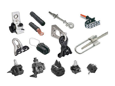
Insulation Piercing Connectors (IPC)
Used For making tap-off/branch connectors/service connector to an ABC line. Insulation Piercing Connectors are designed to make a connection between the uncut main conductor and a branch cable conductor without having to strip either cable to expose the conductor instead the tightening action of the IPC will first pierce the Insulation, then make good electrical contact between the main end and branch conductor while simultaneously insulating and sealing the connection.
Insulation Piercing Connectors are designed to make a connection between the uncut main conductor and a branch cable conductor without having to strip either cable to expose the conductor instead the tightening action of the IPC will first pierce the Insulation, then make good electrical contact between the main end and branch conductor while simultaneously insulating and sealing the connection.
The housing shall be made entirely of mechanical and weather resistant plastic insulation material and no metallic part outside the housing is acceptable except for the tightening bolt. Any metallic part that is exposed must not be capable of carrying a potential during or after connector installation. Screws or nuts assigned for fitting with IPC (Insulating Piercing connector), must be fitted with torque limiting shear heads to prevent over tightening or under tightening (min & max torque values to be specified by Manufacturer). The IPC must perform piercing and connection on Main and Branch cable simultaneously. The IPCs shall be water proof and the water tightness shall be ensured by appropriate elastomer materials and not by grease, gel or paste alone. Design of IPC should be such as to not cause damage to insulation of adjacent conductors due to vibration and relative movement during service. The connector shall have a rigid removable end cap which can be slide fitted onto the main connector body on either right or left by the installer (depending on site requirement) for sealing the cut end of the branch cable. Once the connector is fitted, it should not be possible to remove the cap without removing the connector.
Anchoring Assembly Clamp (Pole Clamp)
For fitting onto a pole for anchoring the end of a length of ABC, or for a major change in direction.
Anchoring assemblies are used to firmly attach the messenger of ABC to a support and transmit the mechanical tension.
a) At the end of a run or to the supporting structures .
b) At a major change in direction.
For supporting a length of ABC at an intermediate pole in a length, with small angle of deviation.
Suspension Assembly is used for supporting an ABC by installation on the messenger at an intermediate point of support such as a pole. It can accommodate small angles of deviation. Suspension Clamps are used for locking the messenger of the ABC bundle without damaging the insulation or allowing the messenger to become dismounted from the fitting.
ABC Service Main Distribution Box for 6Way Connection
This Distribution Box should be Weather & Moisture Proof & should be able to carry a current according to specified capacity. It can have 1/3-phase input & provision of 4 to 6 nos. of 3-phase or 1-phase outputs. The box should have the provision for special key for locking & Proper arrangement of sealing. The boxes should be assembled on the pole using Metal Tapes & Buckles or Bolts. No. of Boxes per pole may vary with supporting arrangement for more no. of service connections. The Spring used should
be of stainless steel having required capacity to provide suitable pressure in the connector.
Deadend Clamp for HT/LT Cable
Deadend clamp are used to hold & grip the AB cable. Our office clamp are manufactured by using good quality of aluminium alloy that are sourced by known vendor. We design these clamp as per the clinical specification. It is durable, easy to install & satisfactory performance.
Eye hooks
Eye hooks should be designed as to hold suspension clamps and Dead end clamps and to be installed with the pole clamp. Eye-hooks should be made of forged Galvanised steel. The clamps corrosion resistance should conform the standards I.S. 2629 & I.S. 2633. Bolts and nuts should be made of hot dip Galvanised steel according to VDE 0210 and VDE 0212. Ultimate Tensile strength (UTs) of the clamp should 20 KN. Design as per furnished drawing.
Transformer Connection
Bi-Metallic Lugs :
The connection to the transformer should be made with Pre-Insulated lugs for phase and street lighting conductors and with an Aluminum Lug for neutral Messenger. If the Bus-bars-bars are of copper, the Lugs should be preferably Bi-metallic type.
Tap off Connector for 11kv AERIEL bunched Cable T-Connector
For Aerial Bunched cables ST Joint, Tee & Cross Connections
1) Each Connector consists of one MVT Connector along with appropriate number of Single core terminations and sealing sleeves, supplied as one set for one core.
2) The Installer should study and familiarise himself with the various parts before commencing installation
3) A typical completed installation is shown in the adjoining picture, (before shrinking of the insulating sleeves).

